HERE'S THE VIDEO!:
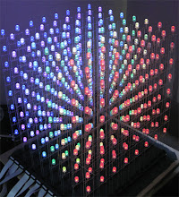
So I've spent more hours then I'd like to admit during the last week trying to get this thing going, including a session until 3am last night but I am very happy to say I think I've nailed it! I've finally got some awesome TLC display driver software running on my PIC32. I've very pleased with my self, so much of what I've learned over the last year seemed to come together and it looks great! Don't get me wrong, there's still a LONG way to go ;) But this is a very important step. This is potentially the end of "hardware development". I do still have a couple of little bugs to iron out, but i'm pretty sure that's to do with cable routing and stuff which should be minor in the scheme of things.
For anyone interested in the technical side, I wanted to try to get the cube to refresh at 100Hz, this meant I would need a layer refresh of 800Hz, since there are 8 layers, obviously. The TLC requires 4096 gray scale clocks (GSCLK) per layer draw so this means I needed a GSCLK of about 3.3MHz.
I used Output Compare modules to generate the GSCLK and also the required BLANK and XLAT pulses at the end of EVERY cycle.
This is something I came up by myself. The other codes I've seen always have a routine to pulse XLAT after the data has finished being sent. But after studying all the signals and with the help of my dad's oscilloscope which he lent me, i realized that my data HAS to send at every layer swap so there's no point having a routine pulse BLANK or XLAT, they just have to pulse at the end of every layer draw, full stop.
So I have the three different pulses set up on three separate output compare modules, and the timer which they are synched to generates an interrupt at 800HZ which then sends the data to the TLCs.
At this point i'd like to say if I didn't borrow my dad's oscilloscope i'd still be guessing what's going on! That thing has been invaluable. Just to be able to see the waveforms and confirm what frequency they're running and stuff like that. I really couldn't have done this without it. Especially the waveforms made by the output compare modules, I'm sure if you decypher the datasheet it has all the details there, but at high frequencies where delays of one clock pulse can make the difference between 2MHz and 3MHz, Trying to work out exactly what the datasheet is trying to say and get it right to the single clock pulse with pen and paper, I just don't have the skill to do that confidently.
If you are attempting something like this, or considering it, buy, beg, borrow or steal an oscilloscope, I don't fancy your chances if you don't at least have access to use one once in a while. This is something i didn't consider when I started this project. Fortunately, my dad has one I can borrow whenever I need.
If you are attempting something like this, or considering it, buy, beg, borrow or steal an oscilloscope, I don't fancy your chances if you don't at least have access to use one once in a while. This is something i didn't consider when I started this project. Fortunately, my dad has one I can borrow whenever I need.
There one other "main" thing to work out at this stage is whether the the way I have the "display driver" code running will allow enough cpu time to run "pattern" software as complex as I imagine i'd like to get it. Either way it shouldn't be terrible; either it can and it's fine, or it can't and I might have to enlist a 2nd uC for the pattern control. That would be another challenge but I think it would be fun too! There are some things I've learned about pic32 which make the idea of doing that no so scary. The main one being no separate DMA memory space!
My "data" was too large to fit into the 2Kb of DMA memory in the pic 24 so the idea of shooting the data between two chips was scary! It would double the amount of data the display chip would have to process, which pretty much defeats the purpose of processing the data on another chip. However the PIC32 doesn't have this limitation, so I theoretically should be able to send it the whole array at a decent refresh rate without the CPU taking a hit at all!
Anyway sorry for the technical ranting.
Also at this stage I'd like to acknowledge some of the inspiration and assistance I've had over the last year. I've got a while to go yet but it's probably something I should have done a while ago.
If you are thinking of building a big RGB LED Cube, this is pretty much a road map so far of the journey I've made.
First of the bat "chrmoe" and his amazing instructable:
This is what really got me started in LED cubes and microcontrollers. I've dabbled in electronics before this point, but never programmed a chip my self. I completed this project and knew straight away that this was just the beginning. So thank you very much chrmoe, you rule!
I also have to mention the awesome folks at avrfreaks.net even though I betrayed them and moved to PICs. When I was doing the above project and experimenting myself with the code, the help I got from that forum was awesome. The people there are some of the most helpful, witty and funny people I've come across a internet forum anywhere!
Two users in particular went way beyond the call of duty to help me out, JS and Kartman, thank you both!
Next is the
This thing is awesome! This is really what inspired me to build my own RGB cube. I still had no idea how I was going to do it, but I knew I had to give it a shot! My cube assembly is pretty closely modeled on the build documents available at the hypnocube site. I came close to buying one of these but really wanted the challenge of doing it for myself, plus i wanted to go BIGGER! If you don't have a spare year to waste ;) then this is the way to have your own cube without developing it from scratch. It's easily the nicest RGB Cube i've seen for sale.
Then I found Dave Clausen's LED Cylinder.
This project is what I based my basic control design on. Using MOSFETs on the high side and TLC5940 LED drivers. Also seeing his code helped in creating my software.
Next acleone and his Arduino TLC library.
This code is really what got me started on the control software. First I ported this to straight AVR and eventually to PIC24. Not much of the original code is there, but the process flow is similar. Now I've moved to PIC32, the code has changed substantially but I wouldn't have been able to do it without what I learned from this code.
Last but not least Matt Padina and his book
Which was pointed out to me only recently by someone who had read this blog. This document was really the icing on the cake! It came at precisely the right time and gave me precisely the right information. It let me rewrite a few key issues in my code and make it heaps more efficient. Without it i might still be struggling to get the PIC32 up to speed.
So to all of the above, thank you very much! If I've forgotten someone please forgive me, i didn't get much sleep last night ;)

That looks awesome, congrats!! I have even deeper cube envy now.
ReplyDeleteThanks for sharing the details of what you observed with the scope and the logic you used to figure out GSCLK... I had been wondering about that myself.
Maybe I could ship you a couple of blades worth of LED's to solder up for me since you're going to have so much free time now! ;)
jas
Hey thanks Jason:) I'm not putting the gloves down just yet, once the hardware is finished, there's going to be lot's to do in software. I'm thinking I might even try to get buttons involved, and maybe even a usb connection to my PC..
ReplyDeleteWhat I'd like to do now is work out how to feed the files I found on this site into my cube:
http://3dleds.com/cube.html
I don't think I'll be using this method in my approach, but after a year I'd really love to just see some pretty patterns on it :)
USART as SPI you say? That's very interesting, I've never heard of it.. **going to look up PIC datasheets**
"USART as SPI" *Matt* says. I can barely spell SPI still! ;)
ReplyDeleteI've poked around a little on the topic tonight... Here's a link to a doc by Atmel that I THINK describes it. I didn't see anything obvious jump out for PIC when I was searching, but perhaps there's a parallel.
Your link above was another one I hadn't seen. (Thought I had seen them all several times!). There's an LED sphere video on one of that site's pages that is pretty cool. Hard enough to do a nice square cube!
Yeah, I bet you're pretty anxious to see yours in full action. I totally would be too! USB to PC would be very cool. The guys doing the Winamp spectrum analyzer on their cube are feeding over USB I believe. Cool stuff.
Your cube looks really great! Thanks for sharing. I'm considering to build such a as an assignment in school. But since I'm new on microcontrollers, this is probably to hard to start with.
ReplyDeleteHow much time did you need for the hardware? What do you think, how much time would you need least (if you would hurry ;-))? Where did you get the leds? I'm afraid that 512 RGB Led's are not that cheap...
This comment has been removed by a blog administrator.
ReplyDelete